Рекламные объявления:
Продажи от Vasilich: Калькуляторы для iProgGuard и iProgPRO. STool - Программа восстановления одометров. PCMflash - загрузчик для блоков управления двигателем
Внимание всем владельцам iProgGuard, iProgPro, с 01.02.2026 начато обновление ЗИМА 2026. <- Читаем это обязательно. Запуск кальков на Win7(64bit).
MasterEditPro - редактор калибровок ЭБУ
Важная информация по PCMflash, читать обязательно. По оплате STool и PCMflash - читать внимательно, потом не жаловаться


Shapovalov
-
Постов
7704 -
Зарегистрирован
-
Посещение
-
Победитель дней
130
Тип контента
Профили
Форумы
События
Весь контент Shapovalov
-
Фигня,ставили с разборки в разнобой. Регулировка форсов(новый рем.к-кт.),ГРМ (метки),момент впрыска(по компу),а там уже и проиводительность турбы. Можно и наоборот...
-
Дунь "эфиром" при запуске , если ДВС заведётся и будет работать на инъекции ,то с мотором всё ОК.
-
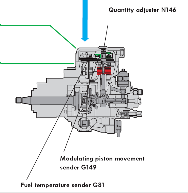
Quantity adjuster N146 The quantity adjuster is integrated in the distributor injection pump. The task of the quantity adjuster is to generate the correct injection quantity from the control signals. The quantity adjuster is a solenoid, a type of electric motor which adjusts the position of the modulating piston via an eccentric shaft and thus regulates the fuel quantity continuously from zero to max. delivery rate. Три последних абзаца в статье перечитай.
-
Где адрес кинул,смотрел? Там про: В статье описывается методика проверки и восстановления работоспособности комбинированного механизма управления количеством топлива (далее МУКТ, мой © ;)))), состоящего из датчика G149 и актуатора N146 на примере ТНВД типа vp37, vp34 (например, VAG 1.9 TDI, 90 и 110 лс). Автомобили VAGcom-om на не VAG-овских моторах настраивать не получится, придется замерять напряжения вручную. В принципе инструкция годится для любых vp с индуктивным или ползунковым G149. Для выполнения этой работы крайне рекомендуется моторный тестер типа VAGcom. Написано по материалам dieselschrauber.de
-
При прокруте движка обороты видит? Может,цепь порвалась? Это не редкость для него.
-
Прогретая и на ХХ зайди в 11к. через "базовые" - во втором окне будет менятся ВКЛ. и ВЫКЛ. В это время и шток турбины должен двигаться и занимать позиции ВКЛ. или ВЫКЛ. А в третьем окне увидишь надув.
-
здесь посмотри:http://info.auto.ru/diesel/faq/article/718.html 04F4 - Дозатор топливоподающего насоса-N146 02FD - Датчик перемещения регулировочного золотника-G149
-
И как в Эльзе или других справочниках с такими номерами ошибок можно найти инфу по ремонту? Тока ВАГ КОМ !
-
ВАГ ком 311(безплатное ПО) с К/Л адаптером - показал бы истинную картину.
-
P1186 FTS Low - Fuel Pump Temperature Sensor Low. В профиле место жительства укажи.
-
"Евро форд" + "супер 16" и увидеть можно многое.
-
К проверкам требования тоже разные;одно дело на утечку и другое на принадлежность к группе.Разные и калибровки в поколениях CR и производителях.Коды тоже не стоят на месте.Тут с поддержкой и обновлениями изготовителя оборудования не ошибиться бы...
-
Нет,имеется ввиду: Прав нет посмотреть . Но очень хочется! Если не трудно отправте на мыло . Так зайди:http://www.deniss.com.ua/content/40.html
-
Нет,имеется ввиду:

-
QR это Denso, програмируются или дилером или DST-PC DST-PC работает с другими системами производителей:Делфи,Сименс,Бош? Интересует прописка форсов и диагностика.Вроде,пишут,что спектр марок расширяется.На презентации этого прибора ты был?
-
Виртуальный доступ к КТС не лепится? Может у кого есть решения? Вань,коды QR применимы к форсункам каких производителей?И какими сканерами программировать эти коды?
-
На сайте написано,что * Для Ford адаптация блока управления насосом PSG 5 через CAN 1 684 463 652 только с адаптером * Только в сочетании с адаптером UNI 4, 1 684 463 539
-
Расходомер к замене.
-
Случаем не 0171 и 0174 ?
-
А чем ты его мучаешь?Ланчем?
-
За панелью приборов.А диагностика его,что не видит?
-
А этой ошибкой что,не появляется уже? 0251 Injection Pump Fuel Metering Control “A” Malfunction (Cam/Rotor/Injector) P0251-CP3 PUMP REGULATOR CONTROL When Monitored: When the ignition is on. Set Condition: The ECM detects a discrepancy between the PWM supplied to the Electronic Fuel Control Actuator and the PWM returned from the Electronic Fuel Control Actuator.
-
P1231 Fuel Pump Secondary Circuit Low, High Speed P1231 Fuel Pump Secondary Circuit Low, High Speed (VLCM) С разных источников. Попалось и такое:P1231 Injector Circuit Cylinder 4 Intermittent. Мало вероятно,но не исключено.
-
Случаем,при ударе модуль насоса в баке не оторвало?
-
Зачем заслонка открывается,при подсосе воздуха в бензинках? При перетянутых форсах и низкой компрессии блок тоже будет пытаться исправить положение,но как умеет.