Рекламные объявления:
Продажи от Vasilich: Калькуляторы для iProgGuard и iProgPRO. STool - Программа восстановления одометров. PCMflash - загрузчик для блоков управления двигателем
Внимание всем владельцам iProgGuard, iProgPro, с 01.02.2026 начато обновление ЗИМА 2026. <- Читаем это обязательно. Запуск кальков на Win7(64bit).
MasterEditPro - редактор калибровок ЭБУ
Важная информация по PCMflash, читать обязательно. По оплате STool и PCMflash - читать внимательно, потом не жаловаться


Shapovalov
-
Постов
7704 -
Зарегистрирован
-
Посещение
-
Победитель дней
130
Тип контента
Профили
Форумы
События
Весь контент Shapovalov
-
-
-
Во впускной бензина со шприца - заводится?Сигналка нештатная есть?
-
-
С такими симптомами неисправности легко ловится(конкретная форсунка)на рядных мерсовских моторах.Газанёшь и как заглохла сразу сканером ошибка читается типа: 0203,0201...В этом случае,видимо,ещё и травили при тесте на герметичность обратки + вероятно,излишние требования в гарантии диагноза - вот ребятки и приговорили все четыре форсунки.А ошибки по регулятору другими цифрами "радуют": P0087 Fuel Rail / System Pressure - Too Low P0088 Fuel Rail / System Pressure - Too High Гельмут,по возможности,узнай чем закончилось?
-
Дилеры могут и с херовыми датчиками выставить её ровно,до первой просадки АКБ. А в "народе" нет алгоритмов калибровки,если идёт речь о пневмоподвеске.
-
Датчик фаз меняй (новый уже по замене с "косичкой" будет) и только родной.А датчик К/В с БМВ подходит,но не в нём причина.
-
еслиб форсы текли он бы хрен заводился Гелен 4.0л.CDI попадался с такими симптомами и тоже фосунку меняли.
-
Спасибо,в "копилку" ещё одна заметка...
-
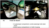
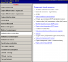
Audi Q7 Quattro V6-3.6L (BHK) Copyright © 2009, ALLDATA 9.90 Page 1 Control Module HVAC: Service and Repair Front A/C Control Head Climatronic Control Module J255, Notes, Removing and Installing Front A/C Control Head Climatronic Control Module J255, Notes, Removing And Installing General notes on front A/C control head Climatronic Control Module J255 - The front A/C control head Climatronic Control Module J255 is available in different versions, "Comfort" and "Basic", and there are differences of these versions again. Therefore follow allocation exactly when replacing front A/C control head Climatronic Control Module J255: Parts Catalog - "Comfort" version of front A/C control head Climatronic Control Module J255 with the "component safeguard" function may no longer be exchanged in the familiar way, as soon as a front A/C control head Climatronic Control Module J255 "Comfort" version has been adapted once in a vehicle, the component safeguard takes effect. Vehicle Diagnosis, Testing and Information System VAS 5051 in "Guided Fault Finding" function. - If a "Comfort" version front A/C control head Climatronic Control Module J255 with active component protection (anti-theft system) is installed in a different vehicle, only the functions necessary for vehicle safety can still be selected (Defrost, heated rear window, etc.), Comfort functions (direction of air flow, temperature preselector, etc.) can no longer be selected. Vehicle Diagnosis, Testing and Information System VAS 5051 in "Guided Fault Finding" function. - Component protection can only be cancelled by entering specific vehicle data Vehicle Diagnosis, Testing and Information System VAS 5051 in "Guided Fault Finding" function. - At this time, front A/C control head Climatronic Control Module J255 "Basic" version is not equipped with the "component safeguard" function (introduction not yet finalized). - The selected functions are displayed by illuminated LEDs in the various buttons of front A/C control head Climatronic Control Module J255. - Display fields and control buttons on front A/C control head Climatronic Control Module J255 are illuminated by Light Emitting Diodes (these LEDs cannot be replaced). - Front A/C control head Climatronic Control Module J255 is not always connected to terminal "15", therefore after voltage supply interruption (via connector - D -) wait still at least 30 seconds to protect the electronics until the remaining connections are disconnected. - If a new front A/C control head Climatronic Control Module J255 was installed and Basic Setting was not performed, A/C system controls are restricted and this is displayed as a malfunction in DTC memory. Vehicle Diagnosis, Testing and Information System VAS 5051 in "Guided Fault Finding" function. - After replacing front A/C control head Climatronic Control Module J255, perform the follow work steps Vehicle Diagnosis, Testing and Information System VAS 5051 in "Guided Fault Finding" function. - Check coding. - Perform basic setting. - Check adaptation. - Check DTC memory of front A/C control head Climatronic Control Module J255 (and of Rear A/C Control Head (Climatronic) E265, if present). Notes on "Comfort" version front A/C control head Climatronic Control Module J255 - Display unit of temperature display of Climatronic Control Module J255 degrees C or degrees F is specified by the MMI (Multi Media Interface) via the Comfort CAN-Bus system and by the setting entered there. The setting can be modified via the MMI by entering via "Car", "Setup", "Setting" Owners Manual. - A/C control head Climatronic Control Module J255 "Comfort" version - A - is available in different versions (e.g. with or without seat heater button) Parts Catalog. - On the A/C control head Climatronic Control Module J255 "Comfort" version - A -, both control knobs - D - can be pulled off and thereby be replaced individually Parts Catalog. - For a faulty measurement by Instrument Panel Interior Temperature Sensor G56 (installed only on front A/C control head Climatronic Control Module J255 "Comfort" version - A -), check intake grille - B - of trim panel for front A/C control head Climatronic Control Module J255, (it must not be closed) and function of Interior Temperature Sensor Fan V42 Vehicle Diagnosis, Testing and Information System VAS5051 in the "Guided Fault Finding" function. - Front A/C control head Climatronic Control Module J255 "Comfort" version can be set into operation for a certain period of time (up to approx. 30 minutes) after switching off ignition by operating the "Econ, On/Off" button (the operating time is dependent on the battery charge state, it is approx. 10 minutes). Operating instructions Notes on "Basic" version front A/C control head Climatronic Control Module J255 - Front A/C control head Climatronic Control Module J255 "Basic" version - A - is available in different versions (e.g. with or without seat heater button) Parts Catalog. - On the front A/C control head Climatronic Control Module J255 "Basic" version - A -, control knobs - B -, - C - and - D - (rotary control) cannot be pulled off and therefore cannot be replaced individually. - On the front A/C control head Climatronic Control Module J255 "Basic" version, "air distribution", "outflowing air temperature" and "fresh air blower speed" are controlled as a function of the setting of the control knobs - B -, - C - and - D - (rotary control). Front A/C control head Climatronic Control Module J255, removing - Check coding and adaptation of front A/C control head Climatronic Control Module J255 via the "Replace control module" function of 2007 Audi Q7 Quattro V6-3.6L (BHK) Copyright © 2009, ALLDATA 9.90 Page 2 Guided Fault Finding (in the event that front A/C control head Climatronic Control Module J255 is to be replaced). Vehicle Diagnosis, Testing and Information System VAS 5051 in "Guided Fault Finding" function. - Switch off ignition. NOTE: - The removal of both front A/C control heads Climatronic Control Module J255 is identical for both "Comfort" and "Basic" versions. - Front A/C control head Climatronic Control Module J255 - A - is held in the center console via retaining clips - B - (on lower side) and - C - (on upper side). - Clips - C - are installed on upper side (form-fitting clip with an angle of approx. 65 degrees), clips - B - on lower side (force-fitting clip with an angle of approx. 120 degrees). Clips - C - must be disengaged in order to remove front A/C control head Climatronic Control Module J255 (e.g. using a small screwdriver after removing CD Changer R41). - Remove "center" instrument panel vent - A -. NOTE: "Center" instrument panel vent - A - is secured in center console via clips - D - and - E -. Insert e.g. Hook 3438 - B - into holes - C - of instrument panel vent and pull instrument panel vent out of center console. - Remove CD Changer R41 - F -. NOTE: Depending on equipment, a storage compartment or another component may be installed, removing. - Using two small screwdrivers - A -, disengage catches of both top clips - C - (above slots in instrument panel center section - D -), then grasp under front A/C control head Climatronic Control Module J255 - B - and carefully pull it out of center console. - Disengage catches of connector - D - by pressing retaining tabs - F - and disconnect this connector. - Wait 30 seconds (to protect electronics in front A/C control head Climatronic Control Module J255). - Disengage connector - E - and disconnect it. - Disengage catches of connectors - A - to - C - by pressing retaining tabs - F - and disconnect them. NOTE: This illustration shows connectors on a front A/C control head Climatronic Control Module J255 "Comfort" version with optional equipment "heated seats". On the "Basic" version, connectors - A - and - C - are not present, on vehicles without "heated seats" as optional equipment, connector - E - is not present. Installing front A/C control head Climatronic Control Module J255 - Check clips - B - and - C - on front A/C control head Climatronic Control Module J255. NOTE: Only install a front A/C control head Climatronic Control Module J255 - A - on which clips - C - (form-fitting clips with an angle of approx. 65 degrees) are installed on upper side and clips - B - on lower side, otherwise front A/C control head can only be removed again when the instrument panel center section has been removed (clips - C - cannot be released on the lower side). Install front A/C control head Climatronic Control Module J255 (install in reverse order). - Perform basic setting, coding, adaptation (and output Diagnostic Test Mode (DTM) if necessary) on the A/C system. Vehicle Diagnosis, Testing and Information System VAS 5051 in "Guided Fault Finding" function. - Check DTC memory of front A/C control head Climatronic Control Module J255 (and of Rear A/C Control Head (Climatronic) E265, if present) and erase DTCs displayed if necessary. Vehicle Diagnosis, Testing and Information System VAS 5051 in "Guided Fault Finding" function.
-
Тесты на утечку и поиск протекания из магистралей сам владелец проводил? "P0093 - Fuel System Leak Detected - Large Leak". Тоже имею не праздный интерес.Цифры замера давления в рампе сканер предоставил или мультиметром с датчика давления сняты?
-
1564 Injection Pump Control Module Requesting Reduced Fueling. 1666 Injection Pump Control Module/ECM Crank Reference Synchronization. Кажется,развоздушить его надо и выставить правильно.
-
-
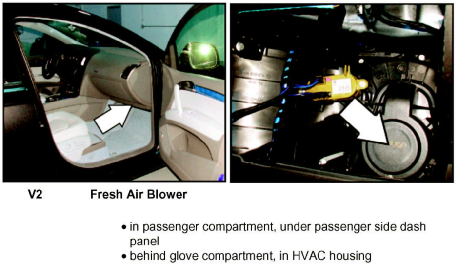
01273 - приточный вентилятор V-2 02095 - включается защита от компонентов Скорее с вентилятором неполадки.
-
-
Если ошибок нет,то ищи подсос воздуха.
-
Недавно наступал в похожее... По кану зайди в сканирование,может и обнаружится где-нибудь ошибка по неправильному кодированию.В моём случае был неправильно закодирован 07 адрес и ошибки по 55 не показывало.После кодирования сразу и обнаружилась.В диагностике темка была недавно.
-
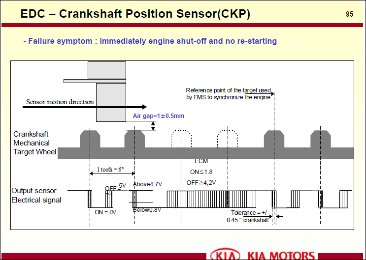
Откуда информация,что давление высокое?Мерять надо.А к ошибке 1181 относится всё это: ※ Pressure lower limit by rpm : 120bar / 800rpm, 180bar / 2000rpm, 230bar / 3000rpm, 270bar / 4000rpm ※ Pressure target value check : (RPS stuck, wiring problem) 350bar / 800rpm, 300bar / 2000rpm, 250bar / 3000rpm ※ Pressure target value check : (fuel leakage, failure from feed pump or high pump) 300bar / 800rpm, 250bar / 2000rpm
-
Другой насос(не закороченый) кинь на провода.
-
P1126 Magnetic Clutch Circuit.
-
Спасибо,огромное!!! Разобрался с этим "гемороем".При правильной кодировке в адресе 55 появляется ошибка по левой адаптивной фаре.
-
Спасибо,Aspirin!А то по Эльзе,как с Иваном Сусаниным... Привет,Бокс!Нет чтоб кинуть инфу,ты только пугаешь GFS.Владелец жаловался,что фары тускло горят,а про замену каких либо блоков не знает.Машина простояла два месяца и сел АКБ.Заменил АКБ и к нам.До этого четыре раза машина на ТО и ремонты приезжала и ошибки этой не было.Терпеть 3 дня не хочет владелец и завтра уже приеэжает. P.S. В 55 адресе ошибок нет и исполнительные проходит.Ошибка только в 07.
-
Не приходилось бороться с такой ошибкой.Предполагаю,что кодировку в 07 нужно сделать,вероятно менялся какой нибудь блок(это я расспрошу владельца).Отправил на 3 дня,чтоб подготовится. ХЕЛП !!! Вин:WAUZZZ4E94N019787.
-
Уже с месяц применяю такой.Навыков с осцилком нет,а этим просто и быстро.
-
В теме дизельной на этот вопрос быстрей ответят.Вот оттуда одна из тем:http://www.oktja.ru/forum/topic/70643-ford-tranzit-kuda-kopat/ По ошибке у меня только это: 1178 Boltup Limits.