Рекламные объявления:
Продажи от Vasilich: Калькуляторы для iProgGuard и iProgPRO. STool - Программа восстановления одометров. PCMflash - загрузчик для блоков управления двигателем
Внимание всем владельцам iProgGuard, iProgPro, с 01.02.2024 начато обновление ЗИМА 2024. <- Читаем это обязательно. Запуск кальков на Win7(64bit).
MasterEditPro - редактор калибровок ЭБУ
Важная информация по PCMflash, читать обязательно. По оплате STool и PCMflash - читать внимательно, потом не жаловаться


Shapovalov
-
Постов
7654 -
Зарегистрирован
-
Посещение
-
Победитель дней
125
Тип контента
Профили
Форумы
События
Сообщения, опубликованные Shapovalov
-
-
Клиент говорит что в даное время утром акум садит почти в ноль пока заведет, а что дальше будет , вперенди не лето.
Вот ковырни ему три болта на распредвале.Буковки мотора не забывай писать,этож не американская автотехника.
Это же не PD, а простая тди.
Год 2005(если верить автору) ,буквы мотора никто не знает.
В заглавии мануала такая надпись:
1.9-Liter TDI Engine
with Pump Injection
(Pumpe Düse)
Design and Function
Self-Study
PD имеется ввиду (Pumpe Düse) ?
-
колега это понятно с кодами только куда копать блок двигатель,,,или на насосе
Начинай с 1564 ,а вторая часто и без повода прилагается.
P1664 (dual-module system - injector drive module (IDM) malfunction; single-module system -
powertrain control module (PCM) malfunction)
• NOTE:Ignore this trouble code if it occurs in conjunction with other trouble codes. Diagnose the
other fault codes first.
-
Клиент говорит что в даное время утром акум садит почти в ноль пока заведет, а что дальше будет , вперенди не лето.
Вот ковырни ему три болта на распредвале.Буковки мотора не забывай писать,этож не американская автотехника.
-
Город в профиле указал , температура утром +5 , датчик менял непомогает...
+5 и ниже - начинается прогрев свечами.А при снятии разъёма блок видит -40 и подаёт соответственно топлива и накал.
-
Если в приборке была ошибка,то датчик t однозначно к замене.Правильность установки впрыска лучше проверить и отрепетировать.Какая t по утрам на улице?
В профиле укажи место жительства.
-
1564 Injection Pump Control Module Requesting Reduced Fueling.
1664 Injection Pump Control Module Malfunction.
-
Между показаниями на моторник и приборку.
-
По ДТОЖ ошибка будет в панели проборов и сразу не регистрируется,если есть расхождение более 5 градусов.
-
Дед,год выпуска и буковки двигателя никогда не мешает написать.
-
...есть шанс отиграть три пачки сигарет!
-
За красной крышкой щупа АКПП .
-
Я же писал тебе как проверять обратку с форсов,которые под крышкой!
Тебе не Старуху надо было(с обилием коммон),а это:http://dimed.com.ua/catalogue/testing_equipment/denso_test/tk_1020dst-pc
-
Спасибо за прикольный ответ! Рад буду пользовать "каширный" софт!
:beeer: :beeer:
-
-
Эта версия в 7 винде работает,как и оригинал?

И ещё вопрос: хотя-бы 311rus(ком портовая) версию оставить можно на компе?
-
В мануалах ниссановских нет ошибки 0135 ,есть только близкие 0133 и 0137.
Каким сканером регистрируется эта ошибка?
-
-
В блоках не копошусь,отдаю ребятам,которые с паяльником дружат.
Может,кто из форумчан подскажет???
-
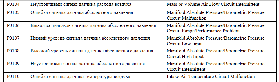
Вот ещё немного:
проверка датчика атмосферного давления
Датчик атмосферного давления (APS) отслеживает изменения давления воздуха и отсылает эту информацию электронному модулю управления посредством изменения напряжения его сигнала.
1. Приложите отрицательный щуп осциллографа или вольтметра к заземлению на двигателе или к заземляющей клемме 1 датчика APS.
2. Соедините положительный щуп прибора с проводом, прикрепленным к выводящей сигнал клемме датчика APS.
3. Включите зажигание.
4. Напряжение сигнала, произведенного датчиком, при нормальном атмосферном давлении (над уровнем моря) обычно составляет 3.0 В. Напряжение будет меняться, отражая изменения давления воздуха, вызванные сменой погоды или перемещением автомобиля в местности,имеющую другую высоту над уровнем моря. Это изменение напряжения скорее всего будет относительно небольшим. Если напряжение не выходит за рамки контрольных значений этого параметра для данной системы, перейдите к следующим тестам.
Сигнал отсутствует.
5. Проверьте питающее напряжение в цепи датчика (обычно оно составляет 5.0 В).
6. Проверьте заземляющую часть цепи датчика. Напряжение в ней не должно превышать 0.25 В.
7. Если заземляющая и питающая части цепи исправны, проверьте целостность выводящей сигнал проводки, идущей между датчиком APS и электронным модулем управления.
8. Если подача питающего напряжения или заземление отсутствуют, проверьте целостность цепи, идущей между датчиком APS и электронным модулем управления.
9. Если проводка APS исправна, проверьте все питающие и заземляющие контакты электронного модуля. Если контакты в порядке, электронный модуль управления предположительно неисправен.
Напряжение сигнала или питающее напряжение цепи датчика равно напряжению аккумулятора.
10. Проверьте на наличие короткого замыкания провод, связанный с положительной клеммой аккумулятора (+) или тот, что подводит к датчику питающее напряжение от электронного модуля управления.
http://mercedes-benz-club.org/forum/archive/index.php/t-1227.html
-
081 Atmospheric pressure 640 hPa - где этот датчик?
Чаще в блоке управления.НО...???
Поищу...
Вот от бензинки такое с манульчика:
6.22. Датчик давления атмосферы впускного коллектора (MAP):
Давление по высоте анализируется с помощью датчика давления расположенного в самом блоке
управления двигателем. Значение при выключенном двигателе (зажигание включено) равно давлению
атмосферы в окружающей среде, и составляет 990 мбар.
Примечание: Если распознается давление по высоте ниже 500 мбар, то прибор управления определит
эквивалентную нагрузку из угла положения дроссельной заслонки. При подаче топлива несколько раз
в неподвижном положении может быть определено неправильное давление высоты прибора
управления.
-
 и продолжение...
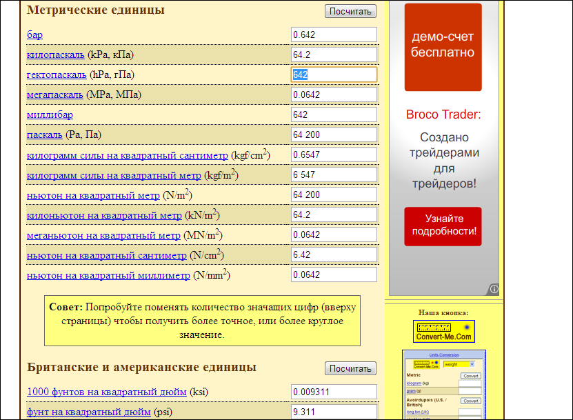
Атмосферное долно быть 100 - 102 килопаскаль.
-
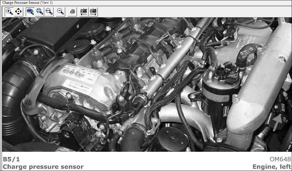
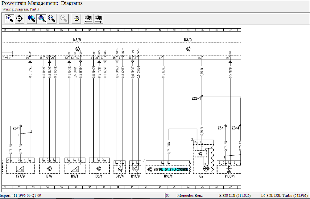
Понятно,этот:

Но это не В28,а В5/1 Charge pressure sensor.
С него показания и от датчика реального атмосферного давления("этолона") - считывается разница.
Если В5/1 нормальный,то получается что показания "эталона" кривые,а блок с "эталона" принимает за основу.
По сканеру должно быть видно атмосферное давление.
-
При ОТКЛ АКБ. При ОТКЛ разъёма датчика педали газа. При ОТКЛ разъёма дросс.заслонки.
-
Про перемычку тоже:
Antilock Brakes / Traction Control Systems: Programming and Relearning
Initialization
INITIALIZATION
1. DESCRIPTION
a. Perform initialization of linear solenoid valve and calibration when the skid control ECU, brake actuator or brake pedal stroke sensor is
replaced. Follow the procedure to perform initialization.
HINT:
- If there is a problem with battery (12 V) voltage, initialization of linear solenoid valve and calibration cannot be completed normally.
Check the battery voltage before performing initialization of linear solenoid valve and calibration.
- If the actuator's temperature is high, initialization of linear solenoid valve and calibration may not be completed normally. If so, wait
until the temperature drops and then perform initialization of linear solenoid valve and calibration.
- If the engine switch is turned off, the brake pedal is operated or the vehicle speed is input while the linear solenoid valve offset
learning is being performed, the learning will be canceled.
2. CLEAR STORED VALUE OF INITIALIZATION OF LINEAR SOLENOID VALVE AND CALIBRATION (WHEN USING
INTELLIGENT TESTER OR TECHSTREAM)
a. Connect the intelligent tester or Techstream to the DLC3.
b. Move the shift lever to the P position.
c. Turn the engine switch on (IG) with the brake pedal released.
d. Clear the stored value of initialization of linear solenoid valve and calibration following the screen.
HINT: Refer to the intelligent tester or Techstream operator's manual for further details.
3. PERFORM INITIALIZATION OF LINEAR SOLENOID VALVE AND CALIBRATION (WHEN USING INTELLIGENT TESTER OR
TECHSTREAM)
a. Connect the intelligent tester or Techstream (with CAN VIM) to the DLC3.
b. Move the shift lever to the P position.
c. Turn the engine switch on (IG) with the brake pedal released.
NOTE:
- If the linear solenoid valve offset learning is performed without turning the engine switch on (IG), the learning process may not be
completed properly because of insufficient battery voltage.
- When the linear solenoid valve offset learning is interrupted, or the learning process is performed with the shift lever not in the P
position, DTC C1345/66 will be stored.
d. Set the intelligent tester or Techstream to Test Mode (select "ABS/VSC/TRAC", "Utility").
HINT: Refer to the intelligent tester or Techstream operator's manual for further details.
e. Leave the vehicle stationary without depressing the brake pedal for 1 or 2 minutes.
2007 Lexus LS 460 V8-4.6L (1UR-FSE) Copyright © 2009, ALLDATA 9.90 Page 2
f. Check that the interval between blinks of the brake warning light / yellow (minor malfunction) changes from 1 second to 0.25 second.
HINT:
- The time needed to complete initialization of linear solenoid valve and calibration varies depending on battery voltage.
- The brake warning light / yellow (minor malfunction) blinks at 1 second intervals during the initialization of linear solenoid valve
and calibration. After it is complete, the brake warning light / yellow (minor malfunction) changes to the Test Mode display, and
blinks at 0.25 second intervals.
g. When the brake warning light / yellow (minor malfunction) changes to the Test Mode display, check that DTC C1345/66, which
indicates trouble with stroke sensor zero point learning, is not output.
h. Enter the normal mode from the Test Mode following the intelligent tester or Techstream prompts.
HINT: Refer to the intelligent tester or Techstream operator's manual for further details.
4. CLEAR STORED VALUE OF INITIALIZATION OF LINEAR SOLENOID VALVE AND CALIBRATION (WHEN USING SST CHECK
WIRE)
a. Move the shift lever to the P position.
b. Turn the engine switch on (IG) with the brake pedal released.
c. Using SST, connect and disconnect terminals 12 (TS) and 4 (CG) of the DLC3 4 times or more within 8 seconds.
SST 09843-18040
2007 Lexus LS 460 V8-4.6L (1UR-FSE) Copyright © 2009, ALLDATA 9.90 Page 3
d. Check that no codes other than ABS code 42, VSC code 45 and electronically controlled brake system code 48, 66, or 95 are stored in
the diagnostic system.
HINT: The ABS warning light and multi-information display do not indicate the normal system code.
5. PERFORM INITIALIZATION OF LINEAR SOLENOID VALVE AND CALIBRATION (WHEN USING SST CHECK WIRE)
a. Turn the engine switch off.
b. Using SST, connect terminals 12 (TS) and 4 (CG) of the DLC3.
SST 09843-18040
c. Move the shift lever to the P position.
d. Turn the engine switch on (IG) with the brake pedal released.
NOTE:
- If the linear solenoid valve offset learning is performed without turning the engine switch on (IG), the learning process may not be
completed properly because of insufficient battery voltage.
- When the linear solenoid valve offset learning is interrupted, or the learning process is performed with the shift lever not in the P
position, DTC C1345/66 will be stored.
e. Leave the vehicle stationary without depressing the brake pedal for 1 or 2 minutes.
f. Check that the interval between blinks of the brake warning light / yellow (minor malfunction) changes from 1 second to 0.25 seconds.
HINT:
- The time needed to complete initialization of linear solenoid valve and calibration varies depending on the battery voltage.
- The brake warning light / yellow (minor malfunction) blinks at 1 second intervals during the initialization of linear solenoid valve
and calibration. After it is complete, the brake warning light / yellow (minor malfunction) changes to the Test Mode display, and
blinks at 0.25 second intervals.
g. When the brake warning light / yellow (minor malfunction) changes to the Test Mode display, check that DTC C1345/66, which
indicates trouble with stroke sensor zero point learning, is not output.
h. Turn the engine switch off and disconnect SST from the DLC3.
Или вот в таком формате:ACE - 2.pdf


X16XEL Vectra B
в Помощь начинающим
Опубликовано
MAP Sensor (Manifold Absolute Pressure),0.27 bar. - что-то ни-то показывает?