Рекламные объявления:
Продажи от Vasilich: Калькуляторы для iProgGuard и iProgPRO. STool - Программа восстановления одометров. PCMflash - загрузчик для блоков управления двигателем
Внимание всем владельцам iProgGuard, iProgPro, с 01.02.2024 начато обновление ЗИМА 2024. <- Читаем это обязательно. Запуск кальков на Win7(64bit).
MasterEditPro - редактор калибровок ЭБУ
Важная информация по PCMflash, читать обязательно. По оплате STool и PCMflash - читать внимательно, потом не жаловаться


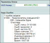
Shapovalov
-
Постов
7653 -
Зарегистрирован
-
Посещение
-
Победитель дней
124
Тип контента
Профили
Форумы
События
Сообщения, опубликованные Shapovalov
-
-
Санёк,а чем ты её диагностишь(или какой V)? "P242F" - такое не встречалось? "Готовность" что показывает?
И в канале форсунок какие показания?
-
Спасибо,успокоил!Уже не верю в "просто решаемые" поломки на ВАГовской группе,последнее время - одни головоломки.Спасибо!
-
Antilock Brakes / Traction Control Systems: Testing and Inspection Procedures
ABS/ESP ITT Mark 20/60
Basic Setting (function 04)
The "Initiating Basic Setting" function 04 does the following for ESP:
Display group number 001 is only necessary for bleeding the hydraulic unit.
In display group number 031, a functional test is performed for the magnetic coil for brake pressure and for the magnetic coil for brake
recognition.
Display group number 040 is required for shutting off the longitudinal acceleration sensor -G251-, e.g. for checking the brake system on a
rolling dynamometer.1)
Display group numbers 060, 063 and 066 are required for zeroing the steering angle sensor, the lateral acceleration sensor and the sensor for
brake pressure.
Display group number 069 is required for zeroing the longitudinal acceleration sensor -G251- 1).
1) Only for All Wheel Drive (AWD) vehicles with Haldex coupling
The hydraulic unit is bled via display group 1 for vehicles with the ESP system. Initiate basic setting.
Basic setting 04 display group number 1 is required if at least one chamber of the brake fluid reservoir has been emptied completely.
Also perform basic setting after repairing leaks in the brake system.
Function 11 "Login-Procedure" is not necessary in this case.
A function test of the magnetic coil for brake pressure and the switch for brake recognition is performed via display group number 31.
This is necessary if:
- Brake booster is replaced.
- DTC memory requests it.
Function 11 "Login-Procedure" is not necessary in this case.
The longitudinal acceleration sensor -G251- is switched off via display group 40
This is only necessary for All Wheel Drive vehicles with Haldex couplings.
Zeroing procedures can be performed via display group numbers 60, 63 and 66.
The steering angle sensor -G85- is zeroed using display group 60.
The sensor for transverse acceleration is zeroed via display group 63.
The sensor for brake pressure is zeroed via display group 66.
Before zeroing via display group numbers 60, 63 and 66, "Login-Procedure" function 11 must first be carried out successfully using the
VAG1551/1552 scan tool for ABS/EDL/ASR/ESP
This is necessary if:
- The ABS control module -J104-, the steering angle sensor -G85-, or the steering column is being replaced.
- The steering angle sensor -G85- is being replaced.
- Adjustments are made to the suspension during a vehicle alignment.
- If steering wheel was removed, perform a zeroing in display group number 60.
- The sensor for transverse acceleration -G200- is being replaced.
- The sender 1 for brake booster -G201- and / or sensor -2- for brake pressure -G214- are being replaced.
- If the DTC table instructs you to zero the sensor based on a DTC in DTC memory of the ABS control module -J104-.
The longitudinal acceleration sensor -G251- is zeroed via display group 069.
This is only necessary for All Wheel Drive vehicles with Haldex couplings.
-
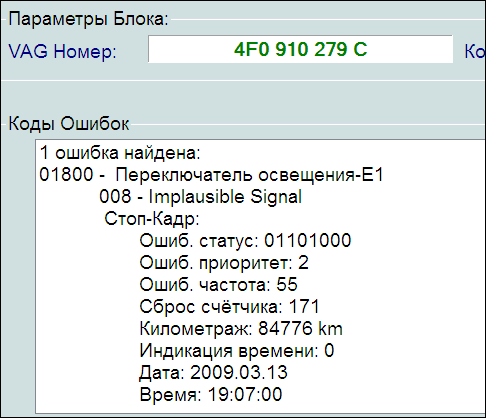
Не могу найти инфу по этой ошибке.Вина переключателя Е1,или всё-таки кодировками исправлять надо?Владелец говорит,что раньше свет не горел (при запуске мотора).После ремонта света фар это стало.Где ремонтировал не признаётся.Прошу помощи!!!
-

Computers and Control Systems: Component Tests and General Diagnostics
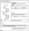
Engine Speed (RPM) Sensor, Checking
Engine Speed (RPM) Sensor, Checking
Function
The Engine Speed (RPM) Sensor -G28- detects engine speed and reference marks. Without an engine speed signal, the engine will not start. If the
engine speed signal fails while the engine is running, the engine will stop immediately.
Recommended special tools and equipment
- V.A.G 1526 multimeter or V.A.G 1715 multimeter
- V.A.G 1594 connector test kit
- Wiring diagram
Test requirements
- Ground (GND) connections between engine and chassis must be OK.
- Ignition switched off.
Test sequence
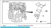
- Disconnect gray 3-pin harness connector (arrow) to Engine Speed (RPM) Sensor -G28-.
- Measure sensor resistance between terminals 2 + 3 at connector to sensor.
Specified value: 480 to 1000 Ohms
- Check sensor for short circuit between terminals 1 + 2 as well as 1 + 3.
Specified value: infinite Ohms
If specified values are obtained:
- Check wiring.
If specified values are not obtained:
- Replace Engine Speed (RPM) Sensor -G28-.
- Erase DTC memory of Engine Control Module (ECM), Diagnostic mode 4: Reset/erase diagnostic data. See: Scan Tool Testing and
Procedures/With Generic Scan Tool/Diagnostic Mode 4: Reset/Erase Diagnostic Data
- Generate readiness code.
Checking wiring
- Connect test box to control module wiring harness, connect test box for wiring test. See: Reading and Clearing Diagnostic Trouble
Codes/Scan Tool Connecting/Test Box, Connecting For Wiring Test
- Check wires between test box and 3-pin connector for open circuit according to wiring diagram.
Terminal 1 + socket 108
Terminal 2 + socket 90
Terminal 3 + socket 82
Wire resistance: max. 1.5 Ohms
- Also check wires for short circuit to each other.
Specified value: infinite Ohms
If no malfunctions are found in wires:
- Remove sensor and check sensor wheel for secure fit, damage, and run-out.
NOTE: There is a larger-sized gap on the sensor wheel. This gap is the reference mark and does not mean that the sensor wheel is
damaged.
If nothing seems to be wrong with the sensor wheel:
- Replace Motronic Engine Control Module (ECM) -J220-.
-
-
P1560 - Cruise Control - Transmission not in Drive
P1560 - Transaxle Not in Drive - Cruise Control Disabled
Это с разных ресурсов.Проверь круиз.
-
-
-
Свечи 1 и 3 цилиндра и катушки лучше-бы проверил.
Впрочем,каждый сам выбирает себе "Ивана Сусанина".
-
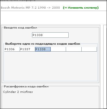
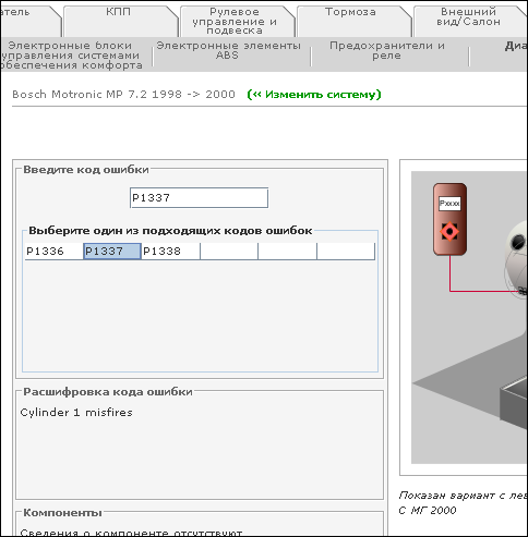
1336 - множественные пропуски по цилиндрам.
1337 - 1 цилиндр. 1338 - 2 цилиндр. и т.д.
Утверждать не буду,лягушатину не ем.
-
1996 BMW 750iL (E38) V12-5379cc 5.4L SOHC (M73) Copyright © 2009, ALLDATA 9.90 Page 1
Idle Speed/Throttle Actuator - Electronic: All Technical Service Bulletins
Section C: Defect Code 00 13 04 01 00 and 00 12 08 01 00
(Resetting EML Adaptation Values on all affected vehicles if a component(s) was replaced)
1. Reconnect battery, connect DIS and turn ignition to the on position (engine not running).
2. Select "Engine Power Control".
3. Select "3 Service Functions".
4. Select "5 Reset adaptation values".
5. Select "1 Pedal travel sensor adaptation values".
Page back <-
6. Select "2 Throttle valve adaptation values".
Page back <-
7. Select "3 Cylinder bank synchronization".
Page back <-
Page back <-
8. Select "1 Execute basic pedal-travel-sensor adaptation". Follow the instructions given in order to adapt PWG sensor.
NOTE:
It is important that the accelerator pedal be fully depressed when "kickdown end position" is requested otherwise the status values will not go
beyond status 3.
If status 5 is not reached, turn the ignition off for at least 10 seconds to allow the system to reset. The status value must be at 1 after the
ignition is turned to the on position, in order to allow the adaptation process to be repeated.
Continue to reset the system and repeat the adaptation process until status 5 is reached.
Once status 5 is reached with accelerator not depressed turn the ignition off for 10 seconds. The status value must be at 0 after the ignition is
turned to the "on" position, otherwise the adaptation process must be repeated.
9. Once throttle response has been verified with engine running - clear all faults set in the EML control module.
-
Заказал термостат и крышку бачка расширительного.Вчера вечером поменяли и заодно эл.заслонки почистили.Гонял весь день и не глушил с утра - всё нормально !!! С адаптацией заслонок пришлось попотеть.КТС не связался ни с каким блоком (а заявленно!).Раза с 25го прошла адаптация "педальным способом" и с секундомером.Обороты плавали с 1200 - 1500. Всем откликнувшимся СПАСИБО !
-
Что значит "Из четырёх машин - 4 блока."?
Как делается прописка шасси, что для этого надо?
1.Из 4 обратившихся на ремонт,закончилось заменой блока.А было только 4 машины таких.
2.Приглашал знакомого (ливанца) со "Снапоном" и он вбивал данные шасси.
-
Блоки у них дохнут,как мухи (особенно не оригинальные).Расположение блока не удачное : жара под копотом и тут-же сырость (в дождь из-под колёс).
Болт разъёма (что по центру) при затяжке с "усердием" выламывает плату блока.При замене блока прописывать шасси надобно.Из четырёх машин - 4 блока.
-
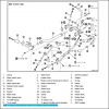
Банальное,как : перетянута с "усердием" пара рейки, или тяги с наконечниками после "хорошей" рестоврации.Кстати,достаточно одних тяг и наконечников "хорошо"реставрированных.Откинуть привод от рейки и мех.часть проверить ,а заодно и отдельно часть с элекро.редуктором.
В зависимости от расположения усилителя.
-

 [a
[attachment=68385:_______________3.png]
 Так и не понял,что это-за машина.Можно только догадываться.С Аллдаты ошибка трактуется по другому;
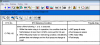

-
Ваня,можно получить информацию по поводу -" обнулять насос " ?
Если инфа закрытая,а настроение располагает - то в личку. Спасибо!
-
-
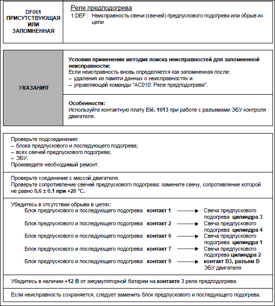
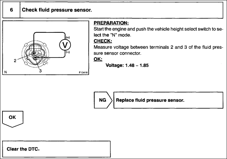
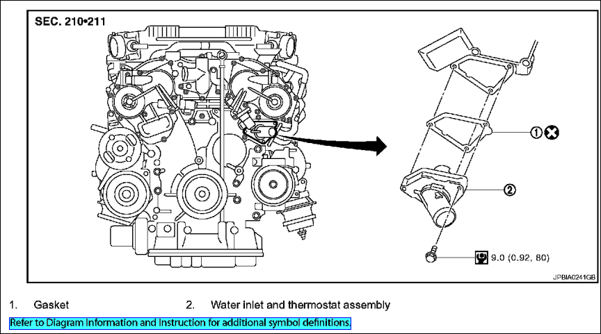
Вот что есть в мануале
Это с ниссановского мануала ?
-
C1762 Air Suspension Rear Height Sensor High (SE) Signal Circuit Short To Battery.
"убежало масло" так там гидроподвеска или пневмо?
-
Аппарата СО не держим и не возникало необходимости.У соседей завтра только одолжу - они ВАЗ,ГАЗ занимаются.
Как правило, после опрессовки, у владельца один вопрос - "а какой цилиндр?". С газоанализатором на этот вопрос не ответить.Нос,конечно,не аппарат,но запаха газов не слышно было из бачка расширительного.
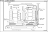
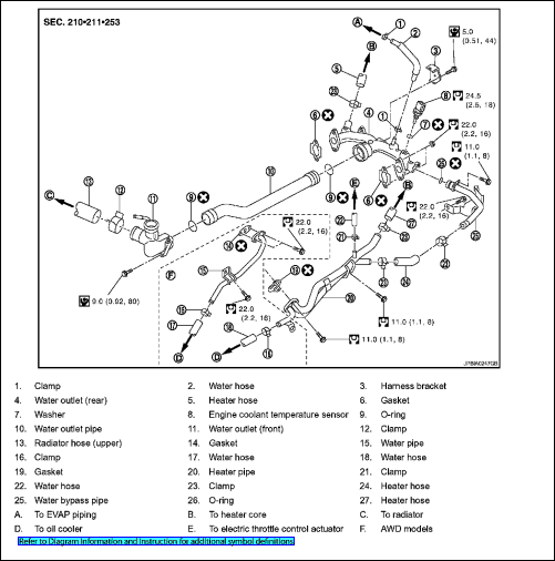
Может у кого есть рисунок системы охлаждения на именно этот мотор ???Аллдата - хорошо,а с другого ресурса может,что и прояснится.
Спасибо !
-
Мотор тоже облазил и ничего, подобного второму термостату, не нашёл.
Снова нужна помошь ! Любой совет принимаю !
-
С Аллдаты,вроде,сдесь нет этого...


Renault Megan Scenik 2000gw.gdi
в Дизели и их диагностика
Опубликовано
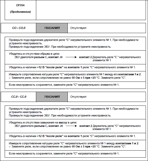
Первую страницу ошибки 094 в запарке не отправил.